10 Facts you need to know about double regulating valves
29 November
Here at FloControl we regularly receive enquiries for Double Regulating Valves for the use in hydronic systems. The term “Double Regulating Valve” is often used as a container phrase for manual balancing valves, but there are product variations, which serve a different purpose in the hydronic system. We have found that quite often the product variations are not understood, which can lead to complications further down the line onsite, if the wrong product has been purchased. Let’s take a closer look at the various manual balancing valves and what they are used for.
5 FACTS RELATED TO THE PRODUCT TYPES
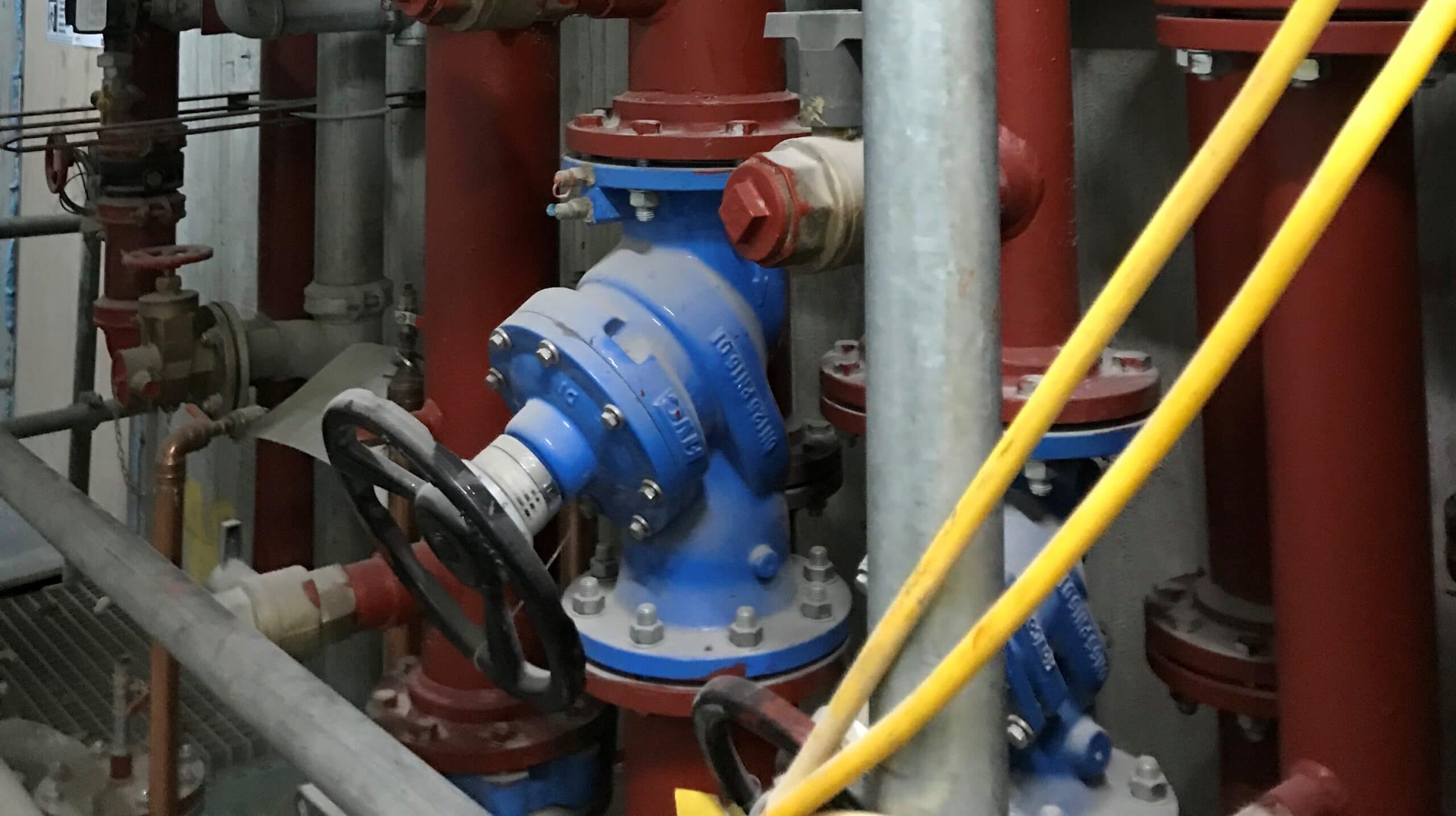
1. The Term “Double Regulating” was coined in the UK and simply means a valve capable of being set to a desired degree of opening, locking that position with a memory stop to ensure the position can be retrieved exactly after the valve has been closed.
2. In the UK the Double Regulating Valve [DRV] is primarily used to create flow resistance or a pressure drop in the by-pass of a 3-Port mixing or diverter valve or for simulating a load for a future loop.
Keep in mind that this balancing valve doesn’t provide any flow measurement. For line sizes from DN 65, Butterfly valves that have been fitted with a memory stop can offer the same functionality as the traditional globe design while being lighter, smaller, easier to install and less costly.
Simple DRVs with memory stop


3. The DRV is sometimes referred to as “Variable Orifice Double Regulating Valve” [VODRV]. This is particularly relevant in countries other than the UK where this valve is used as a Commissioning Valve for commercial reasons. Although the cost of purchase is lower, the commissioning cost is potentially higher because of the complexity of establishing the flow rate. The flow rate is calculated using the Kv value for each handwheel setting and the ΔP across the valve. The flowrate can be established using graphs or a specialist flow computer.
The orifice is effectively the seat/disc assembly within the valve. The space between seat and disc is different for each handwheel position. The flow coefficient (Kv) changes depending on the handwheel position.
The VODRV can be identified by the position of the test plugs, which are located on the inlet and outlet of the valve used to measure flow across the valve.
The measurement accuracy may be adversely affected by this principle by plus or minus 15%, when close to the minimum set point (25% open as per CIBSE guideline). The valve is unidirectional and the direction of the flow arrow on the valve body must be respected. The setting procedure is a time-consuming process at the balancing stage.
VODRVs


4. The Fixed Orifice Double Regulating Valve [FODRV] is also referred to as Commissioning Valve or Commissioning Valve Set.
These valves incorporate an orifice or a venturi. The flow coefficient Kvs value of the flow measurement element of these valves is fixed. The pressure differential is referred to as a measurement signal. The flow rate is calculated from the measurement signal and the Kvs of the measuring device. The accuracy of this type of valve is typically + 5%, depending on the opening position. The valve with orifice needs upstream and downstream straight pipe lengths to measure accurately. The valve must be installed respecting the flow direction indicated on the body. The setting procedure is quick, easy and accurate. The flow can be read from a manometer or an electronic flow meter with the correct Kvs value for all valves installed in the system.
The FODRV with venturi minimises turbulence and recovers a significant proportion of the pressure loss after flow has passed through it, and can be close coupled, which makes the venturi FODRV suitable for systems with low differential pressure. Some venturi FODRVs are slightly more accurate, +3% than their orifice counterparts. The venturi measuring orifice accelerates water flow, increasing the measured signal, ensuring the significant pressure loss common in other valve systems is recovered as it passes through. Energy is therefore not unnecessarily expended in pressure recovery, making these valves highly efficient.
The Venturi Commissioning Valve can be used at higher flow rates without pressure loss, enabling a simpler and easier commissioning process—especially when used as part of a well-balanced commissioning valve set. No straight lengths of pipe are required either upstream or downstream of the measuring venturi (except immediately after a pump, which cause water turbulence). This can be a considerable advantage in a tight application where space is of a premium and offers a more elegant method of commissioning for modern buildings.
Orifice FODRVs Venturi FODRV


5. Globe-style Double Regulating and Commissioning Valves incorporate flow measurement. Alternatively, these can be assembled with a simple DRV or a Butterfly Valve with memory stop and a close-coupled Orifice Plate or Venturi.
Let’s take a closer look at the options and their Pros and Cons.
Converting a DRV into a Commissioning Set in this day and age is usually considered in a retrofit situation, with a globe-style DRV already installed, when a flow measurement requirement arises due to design changes.
Adding an Orifice Plate or Venturi may be more cost effective and quicker than replacing the entire valve with a FODRV. Be mindful that an Orifice Plate requires straight pipe length upstream whereas a Venturi can be close-coupled.
For installations where space is a concern, globe-style FODRVs can be challenging to install due to their size and weight and also cost, in particular on larger sizes. The Butterfly & Orifice Plate Commissioning Set could offer a budget-friendly alternative, especially for DN300 up to DN800 or even up to DN1400. Globe-style FODRVs are typically only available in line sizes up DN600.
The weight of the Butterfly & Orifice Plate Commissioning Set is approximately 1/3 of the weight of a traditional Globe-Style valve. The Butterfly Valve will be equipped with a memory stop so when set, it functions exactly in the same way as a Globe-Style DRV.
Butterfly DRV with Venturi FODRV Butterfly DRV with Orifice Plate


5 FACTS RELATED TO APPLICATION
1. The current design trend for heating and cooling systems is based on a variable flow strategy, rendering Commissioning Valves [FODRVs] redundant. Commissioning Valves are not suitable for variable flow and have been replaced by PICVs.
2. Driven by the need for greater occupant comfort, less energy use and simplification of the commissioning process, BSRIA BG29/21 now recommends a variable speed pump strategy for the hydronic system, which requires pressure independent or automatic balancing and control valves to be installed on branches and terminal units.
For heating and cooling circuits BG29/21 now only recommends incorporating a Double Regulating Valve [DRV] and 3-Port Control Valve bypass into the plantroom design, introducing resistance between flow and return in the primary circuit.
The DRV is installed before the pump as a bypass valve, connecting the flow and return branches, to achieve an equal differential pressure across the system and the DRV bypass when the DRV is set.
The pressure drop from Test Point 1 to Test Point 3 must equal the pressure drop from Test Point 2 to Test Point 3.
DRV and 3-Port Control Valve Bypass Design

3. Install a DRV bypass between flow and return to simulate future system load.
The commissioning valve in the flow branch is set to future system load flow rate and the bypass DRV is set to the future load pressure drop thereby allowing commissioning engineers to commission the system based on the load anticipated in working conditions.
DRV Bypass Design

4. In a Variable Flow System, incorporating zone control, the Commissioning Valve [FODRV] can be installed within PICV-controlled zones to balance the flow to each terminal unit within the zone.
PICV-controlled Zone: Each terminal unit within the PICV-controlled zone is fitted with a static balancing valve so that water is distributed proportionally to all terminal units within the zone.
5. While in Variable Flow Systems Commissioning Valves [FODRV] have become obsolete, there is still a fair proportion of legacy systems in use in the UK, designed for Constant Flow. A typical branch design with Commissioning Valves is shown below (BSRIA BG29/11).
Constant Flow System Design

The terminal units are controlled with 4-Port control and Commissioning Valves, with every branch also requiring a Commissioning Valve. While this design works, it is harder to balance. Consider that every terminal unit has to be visited to manually balance the system. If VODRVs have been used, the pressure drop has to be recalculated during the commissioning process, each time a handwheel position is changed. What’s more, the constant flow system also consumes up to 40% more energy and as pumps are constantly working, decreases the life time of these components. To make the constant flow system easier to balance, the Commissioning Valves could be replaced with Automatic Balancing Valves [ABV], which would require separate metering stations.
FAQS
What is a double regulating valve (DRV)?
A double regulating valve (DRV) is a type of regulating valve used in hydronic systems to control and balance water flow. It allows for precise adjustment and can be locked in place to maintain a set flow rate.
How does a double regulating valve function in a chilled water system?
In chilled water systems, a DRV controls the flow rate to ensure efficient cooling. It helps maintain the desired temperature by regulating the amount of chilled water reaching different parts of the system.
What is the difference between a double regulating valve and a balancing valve?
While both valves are used to control flow, a DRV offers the ability to lock the valve at a specific setting, ensuring consistent flow rates. Balancing valves may not have this locking feature.
What does DRV stand for in HVAC systems?
In HVAC systems, DRV stands for Double Regulating Valve, a component used to balance and control water flow within the system.
Where should a commissioning set be installed: on the flow or return side?
Commissioning sets can be installed on either the flow or return side, but placement depends on the specific system design and requirements.
What is a fixed orifice double regulating valve (FODRV)?
A FODRV is a type of DRV that includes a fixed orifice for flow measurement, allowing for accurate flow rate calculations and system balancing.
How does a variable orifice plate differ from a fixed orifice?
A variable orifice plate allows for adjustable flow rates, providing flexibility in system balancing, whereas a fixed orifice has a set opening size.
What is the function of a DRV symbol in system schematics?
The DRV symbol in schematics represents the presence and location of a double regulating valve within the system, aiding in design and troubleshooting.
What is the full form of DRV in HVAC terminology?
DRV stands for Double Regulating Valve, a device used to control and balance fluid flow in HVAC systems.
How does a commissioning valve work in hydronic systems?
A commissioning valve allows for the measurement and adjustment of flow rates during the commissioning phase, ensuring the system operates efficiently.
Still unsure what the best solution is for your application? Contact our engineers [email protected]
Product Images: jtmplumping.co.uk & flocontrol.ltd.uk
Download